

444.800 MHz
103.5 Hz CTCSS tone
A CTCSS tone is required for access and is transmitted during tone access.
Courtesy tone, voice identification message and repeater hang time
are transmitted without any CTCSS tone to accommodate the IRLP link radio.
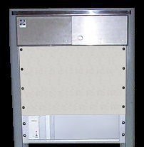 The VE6SBR UHF FM Repeater was constructed from the best parts of 3 old GE Mastr 2 Exec base station radios purchased for $10 each. The repeater, duplexer, receive band pass filter, pre-amp, fans,
and controller are mounted in the upper part of a 6 foot high enclosed 19" rack cabinet Tim, VE6TCJ, gave me. The VE6SBR UHF FM Repeater was constructed from the best parts of 3 old GE Mastr 2 Exec base station radios purchased for $10 each. The repeater, duplexer, receive band pass filter, pre-amp, fans,
and controller are mounted in the upper part of a 6 foot high enclosed 19" rack cabinet Tim, VE6TCJ, gave me.
Receiver sensitivity is .1 uV (12 db SINAD). Audio de-emphases, high-pass filtering of repeat audio and low-pass filtering of CTCSS decoder signal is done with circuits I designed in order to have known, accurate signals to work with. Repeater control is presently done via a simple home brew circuit utilizing standard CMOS integrated circuits. Future plans are for a much more sophisticated micro-processor based controller when I find the time to design and build the "Ultimate Controller". The "Ultimate Controller" is a local term used to refer to the controller of our dreams that we dream of when we are frustrated with what we have and when what we have will not do what we want it to. This controller would obviously be designed around a micro-processor whose software could be modified to provide any possible feature that we could dream up and think that we needed. It would be capable of receiving modified software updates either by a direct hardwired connection, remotely by a phone line connection, link radio or even the repeater receiver itself. Of course, because of great foresight, any additional hardware required to implement newly dreamed up features would already be available on the controller board (or at least the board would be ready to have the, few, readily available, required components soldered or plugged in). And, of course, the cost would be VERY reasonable.... (We can dream can't we?) You never know. . . . Maybe someday it will be a reality. . . . BUT, don't forget whose repeater this is. . . . . . . . . Slowly - But - Surely |

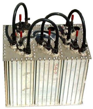 |
This old UHF band-pass filter was the basis for a homebrew band-pass filter. A capacitor was added to each coupler loop to provide reject notches for problem frequencies on the high side of the filter. |
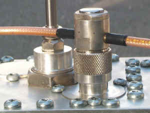 |
Standard "N" clamp type connectors were modified to "T" connectors. |
 |
Holes drilled into the connector body were fitted with brass tubing sleeves sized for the RG-142 teflon cable. The cable was soldered into the brass tubing which in turn was soldered into the connector body
The cable to brass sleeve interface was reinforced with meltable inner wall heat shrink tubing. |
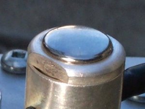 |
A hole filler cap was soldered into the screw in cable clamps. |
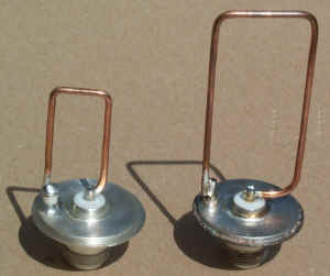 |
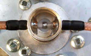
New loop (left) and Original loop (right) The connector mounting plates were drilled and fitted with variable glass capacitors that are added in series with the loops to provide adjustable reject notches. The high quality glass capacitors can each cost $25, or more. I salvaged 6 to 12 from each of ≈ 6 old hand held portable radios that I had saved after intercepting them on their way to a dumpster. (Some have the nerve to call my rescued treasures - junk! Avg of 9 caps/radio x 6 radios = ≈$1200 worth of caps!) |
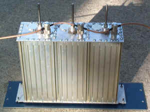 |
The completed filter was mounted on a 19" rack panel for installation into the repeater cabinet. |
 |
 |
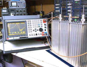
| As you can see, cutoff above the repeater 449.800 MHz input frequency is quite sharp. This was necessary to attenuate several very strong signals in the first 2-3 MHz above 450 MHz. In particular, a 452 MHz repeater output from an antenna only 30 feet away. | |
|